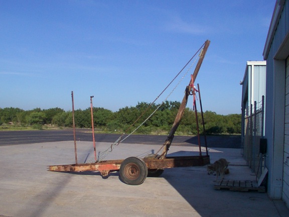
Here I've just about raised the boom to the near-vertical position so that it can be welded in place. The frame is an old farm implement trailer with the front wheels removed.

Here I've just about raised the boom to the near-vertical position so that
it can be welded in place. The frame is an old farm implement trailer with
the front wheels removed.
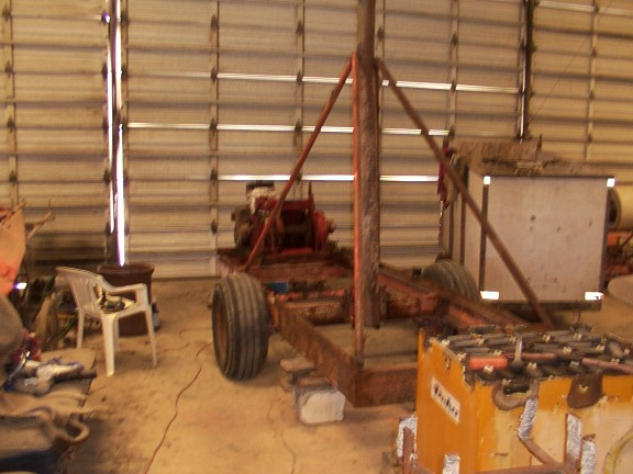
Here the rig is inside, with the 4 braces for the boom attached and the
winch and motor on. Today I've been hooking up the hydraulic hoses to see
if the hydraulic pump will turn the hydraulic motor and run the winch.
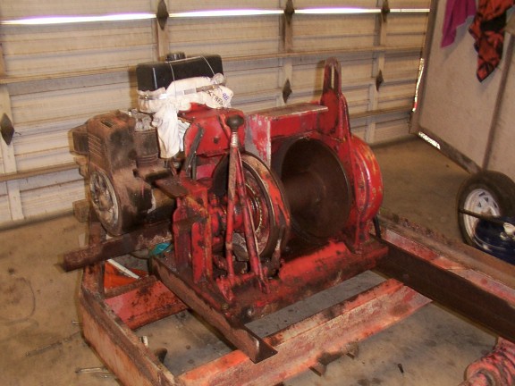
Here the winch is pretty well visible, with the clutch and brake handles
(about the only controls it has) on the near corner. Attached to the winch
with a large hose clamp and a t-shirt for protection is a plastic gas tank
for running the gas engine. If this whole setup works I'll mount the tank
better later.
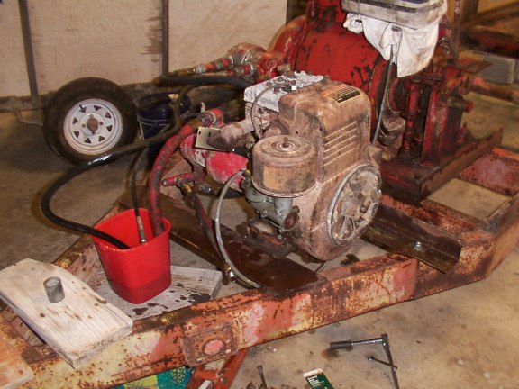
Here the 16HP engine is visible, with the red plastic trash can on the left
serving as the hydraulic fluid tank. The only problem with this setup is
that the fluid returns so quickly through the 1/2" return line that the
hose wants to fly out of the container! I made a nice tank out of an old
freon tank but I picked up a steel welding rod instead of a brazing rod by
accident and goofed up the tank; you're supposed to braze tanks like this so
that junk doesn't scale up on the inside of the tank and ruin it. Oh well;
I'm going to use a plastic bucket or something for the meantime.
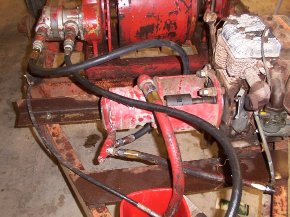
In the middle here is the hydraulic pump that came with the winch. My
friend Dave had given me a 16HP Briggs & Stratton engine (on a riding mower)
years ago and it so happened the bolt pattern on the pump's standoff batched
the engine's. I took the engine apart and got it going, then bought the
coupling to connect the engine's 1" shaft to the pump's 7/8" shaft ($38!).
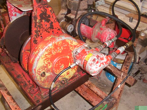
This is a pretty good view of how the hydraulic motor attaches to the winch.
It turns a large gear inside this housing, which is filled with oil for
lubrication. The small line you see coming from the front of the hydraulic
motor is some sort of "seepage" line and goes back to the oil tank, and when
the motor's running a little stream of oil comes out of it.
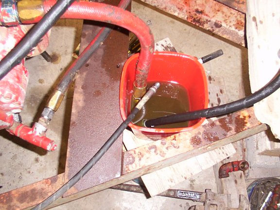
Here's a view into the oil tank, such as it is. The large red hose goes to
the input of the pump; the larger black hose on the right is coming back
from the hydraulic motor, and the small black hose coming from the left is
the seepage line.
The bit has been made out of a 5" and a 6" pipe, one inside the other, with about 2' of sliding action for banging the end in and out of the soil. I'll get a photo of this up soon. This assembly is 12' long and weighs about 500 lbs or so. After some use I feel that 1 foot of sliding travel would be sufficient, since the bottom stops are pretty dinged up and 1 foot would be plenty of travel to unstick it from the bottom of the hole, which is the real purpose of the sliding anyway.
The drilling has proceeded without too much of a hitch, considering the local soil conditions. The first couple of feet we did with a post hole digger, since the ground is very dry and almost impossible to pick up. After that we had to add a bit of water but the bit started coming up pretty full of the clay-like soil we have here. We made good progress down to 14 feet or so.
At that point the soil got so sandy that it just formed a little mound in the middle of the pipe and was about impossible to pick up. What did help was adding bentonite (bags available here and there for $8 per 100 lbs.), which made the soil sticky and clumpy enough to stick inside of the pipe. We have also tried powdered lime and that might be working even better than the bentonite, although the bentonite has the advantage of strengthening the bore walls.
In any case, these last few days it's rained terribly and the water seems to have seeped into our layer of dry sand. There is maybe 9" of water in the bottom of the hole, making the sand ever harder to pick up, although it is possible with enough bentonite.
It's supposed to rain over the next few days, so we will either make a bailer (to bail out the wet sand) or just wait until the rain passes and then bail the water out with something and continue on. We've started to pick up some clay and gravel pieces, so we may basically be through the sand, except for our water problem.
I'll keep you posted! 10/23/2002 23:22
11/10/2002 Well, hmm, it stopped raining on about the 5th but right now there's up to 6 feet of water in the hole. Bailing it out didn't really make much of a dent in the level. As I tell my old driller friend, if it would make water like this all the time, we wouldn't have to go any deeper! In any event, I'm going to see about pumping it with compressed air (see below) just to get a flow rate for this layer established, although basically nothing will come out of it later, after the ground water filters down and away.
Wells are "developed" (the sand and small stuff pumped out of them) by pumping the water with compressed air. A small pipe is put inside of a larger pipe, and the larger pipe fed down almost to the bottom of the hole. The smaller pipe inside of it ends maybe half way between the surface of the water and the bottom of the hole. The depth of the smaller pipe and the diameters of the two pipes in question vary according to the depth of the well, the available air pressure/volume, and the flow rate the well can sustain.
The nice thing about this sort of water pump is that there are no moving parts to speak of. A disadvantage is that it can take quite an air compressor to do much pumping from a deeper well, although I can't quite give you accurate sizes. I can say that a 200 foot deep 14" well takes one of those air-compressor-trailer thingies to blow it out adequately.
Air pumping is even used to pump water from wells on a regular basis. BowJon makes little compressors with windmill blades mounted directly on them which apparently pump water just fine. I like the idea, and again, there are no moving parts down the hole to goof up.
I'll see about pumping this ground water from my hole with a regular shop air compressor soon and report the results back here.
12/01/2002
Well, last weekend we tried pumping water out of the hole with an air hose from my air compressor dropped into a flexible pipe dropped down the hole. However, with 2 feet of water at the bottom of a 16 foot hole, almost nothing got up to the surface. You need a certain amount of water in the bottom of the hole for the air to bubble the water all the way up to the surface.
This weekend things didn't go much better. We dropped a pipe down the hole to take samples, finding our sand, of course, and picking up a few pebbles. Then we notched the sliding bit arrangement so that the inside pipe was locked in the "down" position when dropped, so that all 500 lbs. of bit hit the bottom of the hole at the same time. This didn't seem to make any improvement, as we could see the pipe going down maybe 3 feet into the sand accumulation but never grabbing anything hard enough to pick up that sand and water.
At this point we're about ready to build or rent a rotary rig.
02/25/2003
We made a bailer out of a 2' pipe about 6" in diameter and dropped it down the hole repeatedly. We got 6-7 5-gallon buckets of sand out, along with some rocks ranging in size up to 1". We have decided that, since this hole always seems to have so much water in it at this shallow depth, we will have the water tested and see how it is. It may be salty, but it may not, and although it probably wouldn't have water in a drought, it has certainly had water in it for months now. I am going to get a small electric pump and drop it down there with a garden hose and an extension cord and see what kind of flow the hole will produce. With such a sand cavity down there, we might get plenty of flow. We shall see.